
When It’s Difficult to Get Started
“I can start designing other kinds of metal components, like building-block fabrications and machined-from-wrought stock parts, but it is harder for me to start designing a casting.”
“When we finally get a casting design sent out in a solicitation, most metalcasting supplier teams who respond want to change the design.”
If that sounds like your thoughts and experiences, you are not alone. Before we analyze why getting started with a good casting design is difficult, and how to formulate what can be done about it, let’s talk about “why castings in the first place.” There must be a driving force to design castings, because it is not easy.
There is a driving force, and it is the huge, wide spectrum of highly successful, cost-effective, functionally efficient, structurally durable casting designs all around us. It is obvious to manufacturers that they should emulate those successful designs into their products. But most of those success examples were accomplished by brute force. Trial and error. Fits and restarts. Typically, there was re-tooling, design modifications, and failed first articles, and accumulated launch delays.
Principles of physics, metallurgy, fluid mechanics, heat transfer, and transformed stress control can prevent such grief and make it much easier to start a new casting design efficiently.
There are two pillars in the foundation of excellent casting design, done efficiently the first time:
1. Castability Geometry
This is the mold cavity shape that an alloy flows into and solidifies with temperature distributions and heat transfer that complements the alloy’s metallurgical characteristics of solidification integrity. Metalcasting alloys have an “attitude” about the mold cavity geometry they flow into. That “attitude” varies among the alloys, and the shapes they “like” also vary. Few alloys are “compliant” and will flow into and solidify well in a variety of mold cavity shapes. Most alloys have definite preferences for the shape types they flow into. Some have a “bad attitude” and must be coerced into a better attitude with very specific design geometry principles.
2. Sketch First
While specific to casting design geometry and the resulting mold cavity, metalcasting alloys take their shape as liquid. That means any shape you can conceive is possible. However, all of the 3D CAD software tools take you down a path that limits what you can do with liquid geometry in either the shape itself or the shape’s accuracy as an engineered component (not just a 3D picture).
There are two types of 3D CAD software: Parametric, and Push/Pull. Push/Pull is also known as full-feature surfacing, and it is used to make curvy shapes like castings can be and usually should be. But, Push/Pull doesn’t have the mathematics and analytical geometry behind the surfaces. It is essentially a water-tight surface, devoid of math needed to make it dimensionally accurate or easy to change parametrically.
Parametric 3D CAD, also known as “feature-based,” uses 2D sketch planes to create solids of revolution and extrusion. They are very accurate and can be changed readily via the parametrics of the mathematics and analytical geometry behind the surfaces that you see. They can also have surfacing algorithms that scoop out curvy profiles or add-on a curvy shape. But adding on curvy profiles is tedious, and the basic starting geometry is made up of the building blocks of a fabricated shape, not a casting.
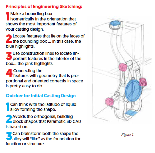
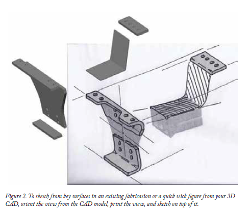
Figures 1 and 2 show how to create isometric, hand-drawn sketches that are proportional and quick to build. Sketch a bunch of them, brainstorming as you go, throwing them all away except the last, best one. Then, make your first-generation solid model.
That’s an overview of the foundation of the design engineering part of an excellent casting. Next is the manufacturing engineering of the design to see if it is producible.
There are also two pillars in excellent manufacturing engineering of a new casting design:
1. Anticipate how the liquid, high-temperature alloy might enter a mold cavity.
As an OEM concept-to-production team, you don’t actually have to choose a mold cavity-making process or anticipate how the tooling for the mold cavity might be designed and constructed. Leave that to the metalcasting supplier teams who respond to the solicitation of your well-executed design and manufacturing engineering.
Manufacturing engineers have three ways to visualize how the hot, liquid alloy might enter the mold cavity that results from your first-generation solid model. What they should seek is the temperature distribution inside the mold cavity and the heat transfer patterns of cooling down that enable the solidification integrity specified by design engineers, and the fit the “attitude” of the alloy they chose.
- Visualize those temperature distributions from views of the model, including 3D views of 2D cross-sections.
- Purchase and learn to use metalcasting industry software that simulates mold filling and solidification integrity.
- The best and most economical and efficient way is to purchase the flow simulation and thermal flow algorithm “add-in” to your 3D CAD software suite. These add-in algorithms, which most 3D CAD providers offer, enable visualization of temperature distribution throughout the mold cavity, and show the thermal flow patterns of the differing temperature regions into the mold walls and the mold’s surroundings.
Among many beneficial attributes of these algorithm add-ins is being able to stay inside your 3D CAD parametrics, so improvements in temperature distribution patterns can be made quickly while remaining inside the software’s part file.
Metalcasting industry software requires an output to an .stl file, from which powerful simulations are made, but the results have to be interpreted visually, and then the original part file modified from visual interpretation.
2. Make only one geometric dimensioning and tolerancing drawing file, not anticipating how the casting would be made and not anticipating what features would be machined and what other features would remain as-cast.
Instead, spend time evaluating the functional requirements, structural wall shape and thickness requirements, and assembly fit-up requirements, feature-by-feature. Then specify the tolerances needed, without regard to how those tolerances might be accomplished. Let your GD&T be a “contract for inspection, not a recipe for manufacture.”
This approach to casting tolerances is very powerful in enabling proposing metalcasting supplier teams to use their process capabilities to offer lower cost net shape alternatives.
The result of the manufacturing engineering of the casting design is the second-generation solid model. It embodies an understanding of the chosen alloy’s “attitude” about the mold cavity shape that it will flow into, cool down, and solidify with the specified integrity.
It embodies a drawing file, toleranced carefully for what is needed, not how it should be made.
That second-generation solid model then becomes the model that is solicited among metalcasting supplier teams. They are then required to offer their third-generation response solid model that not only defines what the finished casting will cost, but also how each respondent would make the net shape casting, and give you insight to their manufacturing capability for this specific casting design.
Click here to see this story as it appears in the January/February 2020 issue of Casting Source.