
Launching New Casting Designs Dimensionally
Problem: “As we launch new casting designs, the prototypes do well, either functionally or structurally. But we really struggle getting production first articles approved, especially dimensionally. We often have to launch production using castings that are not proven capable of being dimensionally correct. Later, when we expect finished, net-shape casting dimensional issues have been put to bed, we are surprised to find that occasional castings have assembly misalignment problems. We rarely get to an assignable cause that reassures us of a robust dimensional compliance solution.”
Solution: There is an opportunity for OEM design teams, especially for the manufacturing engineering role on the team, to mitigate first article dimensional non-conformances. There also is an opportunity for metalcasting supplier teams, especially the metalcaster’s manufacturing engineer and the mold cavity tooling builder, to not only mitigate, but prevent after-production approval dimensional non-conformances.
Geometric Dimensioning & Tolerancing
The OEM design team is typically skilled at applying geometric dimensioning and tolerancing (GD&T) to many kinds of engineered components, but often missed is the powerful benefits of using it in the manufacturing engineering of casting features.
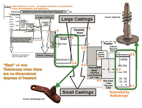
Metalcasters generally think in terms of the old coordinate tolerancing system of plus/minus tolerances, and for good reason. The dimensional capability of their mold cavity-making processes is best expressed in plus/minus tolerances. But the team’s mold cavity tooling builder is skilled at understanding and applying GD&T because it is necessary for the mold cavity to comply with the OEM’s casting design requirements.
No matter how accurately manufactured, no component is perfect. Castings are visually not perfect. They have parting lines, core/slide match lines, little bumps and valleys where liquid metal delivery features were cut off and ground down to be flush with the adjoining as-cast surface. Further, they have draft on some partial or entire surfaces. So, GD&T, which embraces the reality of imperfection, and deals with it for the sake of consistent assembly, is the perfect idea for tolerancing castings.
How the Common Denominator of Opportunity Works When Applied to Castings
Three facets of the ASME GD&T Standard can make a huge difference when applied to tolerancing casting designs:
- The primary datums, A, B, and C, should be as-cast surfaces, with broader tolerances, from which the more accurately toleranced surfaces are defined.
- Because GD&T is “a contract for inspection, not a recipe for manufacture,” simply specify the geometric tolerance type and accuracy needed, and let the metalcasting supplier teams figure out the most economical way to manufacture the finished casting to comply. No need to specify machined features or have a separate casting drawing.
- The two most powerful geometric tolerance types for mitigating casting dimensional non-conformances are position and profile of a surface. These two incorporate much of the entire GD&T standard, and one, the other, or both control a feature’s location, size, orientation, and/or form. While complex-looking, position—especially the position of holes—allows significantly more latitude to eliminate drilling and make casting holes net shape or to minimize machine stock on larger holes, enabling them to be bored to size and location at lower cost.
Profile of a surface enables the process anomalies in casting surfaces that we all know exist but don’t know how to accommodate. Rather than default to the drawing’s title block tolerances (or write an “all other” note) for features that don’t require tighter geometric tolerances, establish profiles on those features that can be loose enough to accommodate the known casting surface anomalies. Then let the metalcasting supplier teams’ innovation in mold cavity-making choice and tooling design and construction comply with the tight geometric tolerances where required and use the looser ones to locate the casting process surface anomalies.
Now, what about the problem of dimensionally approved production castings that are rejected in the OEM’s assembly operation for fit-up problems? The opportunity lies in the application of GD&T in the way castings are processed in their as-cast state.
That application is the use of functional gauges to hold each casting as it is processed in key finishing steps (including machining or fabricating fixtures) that affect its ultimate fit into the customer’s assembly or sub-assembly. The way the castings are held is the secret. Using the primary datums in the same way the casting is aligned in assembly, verify that the casting profiles are correct, not bent, not twisted, not damaged in any non-complying way in the preceding process, be that shakeout, gating removal, gating contact blending, heat treat, whatever. Functional gauges are designed as checking fixtures as well as holding/clamping devices for a manufacturing step like grinding. Unlike sampling important dimensions in statistical process control, every casting is verified for its compliance in assembly at each stage. If a casting doesn’t rest in the functional gauge’s datum-based verification tooling points, it is set aside for a salvage operation.
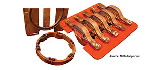
Figure 2 illustrates a functional gauge for a cast steel truck suspension airbag beam. This, among three functional gauges in the finishing processes, verified axle fit-up with each gauge step. It held five castings for the final grinding step. Sixty thousand castings per year passed through this functional gauge and the two preceding ones, with no rejections for axle or airbag fit-up, year after year. And the castings were delivered and assembled as-cast—no machining.
Click here to see this story as it appears in the May/June 2020 issue of Casting Source.