
Improving Part Design for 3D Sand Printing
3D sand printing produces sand mold components without any pattern or core box equipment. The process essentially makes sand molds without the middleman.
To those who have purchased castings for years, this can seem strange. Pattern shops supply patterns and metalcasting facilities pack sand around them to make the mold; that’s the way the industry works.
For the pattern shop to skip the pattern and supply the sand mold instead is a change that customers sometimes have to wrap their heads around. However, this change both simplifies the casting process and overcomes many previous limitations. 3D printing of sand potentially makes casting both more efficient and more effective at the same time.
The 3D printing sand method is an option worth exploring when parts are complex, the order is low volume, reduction of post processing is desired, and concurrent iterations are needed.
Because the cost of 3D printed sand is high compared to sand molds and cores produced using soft tooling, simulation is used to engineer gating and chilling strategies for complex castings rather than doing trial and error development.
Typically, the foundry performs the following steps to produce existing parts using 3D sand printing.
- Scale the solid CAD model for foundry shrink.
- Add required gating and rigging.
- Run solidification on the model design with the gating and rigging.
- Design the 3D printed sand mold.
- Run the STL.
- Transfer data to the printing machine.
- Give the operator visual of the build box.
Often the skill and experience of the person who sets up the files for build will determine how well the build turns out. Successful builds depend upon an effective support strategy, the orientation and location of parts on the build platform, and the number of parts that are built on the platform. To further complicate the planning process, various alloys react differently. Success with one alloy may not guarantee success with another alloy. A degree of familiarity with each alloy and technology being used is required to optimize success.
Designing a brand-new part opens up new opportunities to take full advantage of 3D sand printing. Can two or more castings now be made as one, eliminating joints in assembly, machining and assembly time? Maybe the part can be optimized to achieve better functionality.
With 3D printing, designers can design the exact parts they want. This is the time to look for ways that add complexity, remove unnecessary weight, or improve the performance of the cast component.
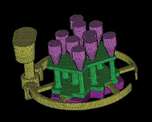
Figure 1 shows a solid model 3D drawing of a casting for optimization in the design stage. The first image is the model input for process solidification modeling. The gray is the gating system, blue-green for risers, and orange for casting. The second image shows the meshed solid model of the casting with the rigging system.
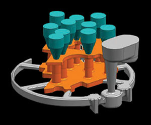
Typical analyses are done at this juncture for fluid flow, velocities, temperatures, solidification fronts, macro and micro porosity and stresses. This system took advantage of 3D sand printing by creating a bottom-fill approach in the runners and gating to avoid metal turbulence in filling.
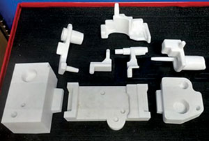
In another example, the production part required a core assembly consisting of eight sections (Figure 2).
Parts were then mated and glued together to print one core. Now, 3D printing allows this part to be printed in a single core (Figure 3).
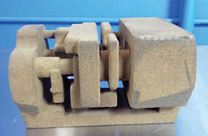
This reduces the number of stacking tolerances, lowers cost, and produces a higher quality complex core. CS
Learn more about designing parts for 3D sand printing with the AFS Institute Live Online course, “Design and Optimization for 3D Sand Printing” June 15-17. Register at www.afsinc.org/instructor-led-training.